Dakota Digital VHX gauge control through BIM-01-2 with GMPP harness. How?
I recently purchased a Dakota Digital BIM-01-2 module to drive the VHX gauges from the LS ECM vs running all new sensors & wires for it. However the GMPP ALDL connector doesn't have the proper terminals available for the DD module to get the signal, instead these wires are in a separate connector in the harness.
So did you add these terminals to the ALDL connector, or connect the BIM module directly to this other connector in the harness to get the BUS signal?
__________________
Scot
86 Monte SS
LS2/T56 Magnum
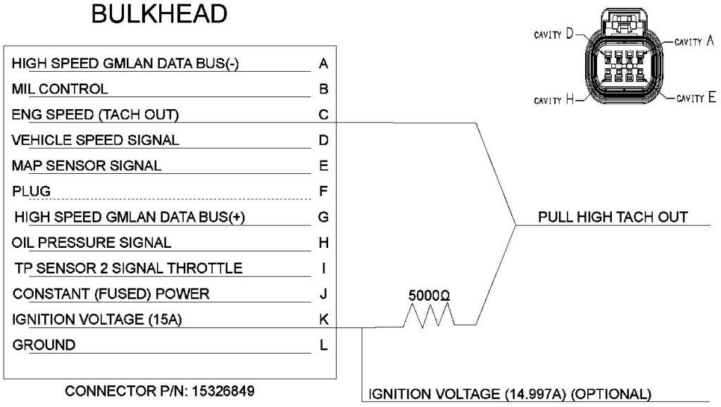
That's what I was going to do, but GM didn't put the two terminals needed to feed the BIM module in the ALDL connector. But they are in the "bulkhead connector". So I either have to wire them to the ALDL connector. Or wire it direct to the BIM module with a RS232 connector.
__________________
Scot
86 Monte SS
LS2/T56 Magnum
That's what I was going to do, but GM didn't put the two terminals needed to feed the BIM module in the ALDL connector. But they are in the "bulkhead connector". So I either have to wire them to the ALDL connector. Or wire it direct to the BIM module with a RS232 connector.
I just connected it and it worked. No mods needed. GM connect and cruise LS3. What two terminals are you referring to? The BIM just reads the OBDII port as far as I know.
Everyone we have done correctly necessary right to OBD port and is done. Easy
Then I guess I have a b@sturd GMPP harness. The wires needed for the BIM module are NOT in the ALDL connector, repeat NOT in it. I sent a pic of it to DD & he told me they are not there. So I have to run new wires for it.
My ALDL connector:
__________________
Scot
86 Monte SS
LS2/T56 Magnum
It looks like you have 6 and 14 populated, that would be can + on 6 and can - on 14.
The GM cars that harness is based off of use the can bus for gauges. I doubt the IPC information is on the serial bus that would be connected to pin 2 on an older OBD2 car.


 Brian Hobaugh SCCA National Tour June 2014
 First Hemi 'Cuda Convertible Ever Built
 Short clips: Goodguys Pleasanton autocross and pit videos


 Linear Mode

